Iranian Classification Society Rules

< Previous | Contents | Next >
III. STRENGTH ASSESSMENT OF LNG CONTAINMENT SYSTEM
1. Containment System Configuration
(1) Layered Foam Type Containment System
(A) The Layered foam type containment system was first introduced in 1970. Gaztransport & Technigaz(GTT)'s Mark III and CS 1 are present.
(B) Membrane tank type of Mark III
(a) The membrane tank composed of a thin membrane is liquid tight. Unlike the in- dependent tank, the membrane tank does not handle the cargo load. Instead the inner hull adjacent to the insulation outside the membrane tank support the load.
(b) The material of primary barrier consist of austenitic stainless steel 304L which is possi- ble to expand and contract in order to absorb the thermal deformation and hull deformation.
(c) The secondary barrier and the secondary insulations is a membrane called Triplex which consists of the aluminum foil attached with glass fiber in and out for watertightness. The secondary insulation is composed of the reinforced polyurethane foam as same as
the first insulation and the plywood. Figure 6 shows a typical cargo of Mark III.
containment system
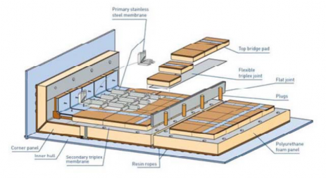
Figure 6 Cargo containment system of Mark III
(C) Membrane tank type of CS 1
(a) Invar is used as the primary barrier.
(b) Triplex is used as a secondary barrier.
(c) The cargo containment system consists of a pre-fabricated panel to support a load. The panel is composed of polyurethane foam and first layer and second layer and the secon- dary barrier. The panel thickness may vary from 250mm to 350mm in order to meed
the BOR requirement. The panel gets in contact with the hull by the mastic. Figure 7
shows a typical cargo containment system of CS 1.
![]()
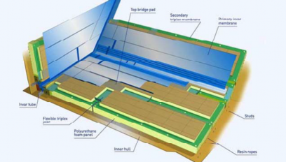
Figure 7 Cargo containment system of CS I
(2) Box Type Containment System
(A) The box type containment system, introduced in 1960, is a typical product of NO 96 by Gaztransport & Technigas(GTT).
(B) Membrane tank type of NO 96
(a) The membrane tank composed of a thin membrane is liquid tight. Unlike the in- dependent tank, the membrane tank does not handle the cargo load. Instead the inner hull adjacent to the insulation outside the membrane tank support the load.
(b)
The membrane material is invar which has the extreme low thermal expansion co-
efficient and the stress does not occur due to the thermal expansion and contraction.
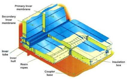
(c) The membrane stress is hardly generated, and not influenced by generate the stress in the adjacent hull structure. Figure 8 shows tainment system of NO 96.
Figure 8 Cargo Containment System of NO 96
the external force to
a general cargo con-
(3) Other Type Containment Systems
The design of cargo containment system shall comply with the international shall be approved by the Society.
gas code(IGC) and
![]()
2. Comparative Method
(1) General
(A) The comparative method refer to a method to evaluate the target ship by selecting the ref- erence ship with a proven service history among the LNG membrane ships.
(B) The comparative method is applied when the strength of cargo containment system of the
reference ship is same with that of the target ship.
(C) The reinforced comparative method is one of the comparative method and is applied when the structural strength of cargo containment system of the target ship increases from that of
the reference ship.
(2) Application conditions
(A) In order to apply the comparative method or the reinforced comparative method, the follow- ing should be proved.
(a) The cargo containment system of the reference ship and that of the target ship should
be substantially equal.
(b) The hull structure supporting the cargo containment system should be quite similar.
(c) The verified navigation record should exist for the cargo containment system of the ref- erence ship or that of similar ship.
(B) If it does not meet the above criteria, the designed cargo containment system is determined to be new design.
(3) Selection of Target Ship
(A) When the reference ship meet the following conditions, it is recognized to have the proved operating record.
(a) The important damage or repetitive damage at cargo containment system should not occur. All the environmental conditions for each filling level should be considered.
(b) Proven service history can be approved for each load height. For example, a good per-
formance for the high filling level can be approved, independent of the good perform- ance for the low filling level.
(B) In order to establish a proven performance record for the new design of cargo containment
system, the information from all sail should be recorded. The minimum required information should include the date, the filling level, the sea state, the ship speed and the wave incident angle. This information is used to evaluate the expected sloshing loads in navigation and compared to the design sloshing load. If the sloshing load during the voyage is similar to the design sloshing load and the cargo containment system is operating as predicted, the Society can approve that the designed cargo containment system have been proven.
(4) Comparative Method
(A) In order to proceed the comparative method, only the design sloshing load of the reference ship and that of target ship is needed. The design sloshing load is obtained through the
CFD analysis or the model test, the structural analysis is not required.
(B) The design sloshing loads of the reference ship and that of the target ship should be ob- tained in the same manner. The model test should proceed following the same procedure with the same model test facility.
(C) If the design sloshing load of the target ship is lower than that of the reference ship as shown in Figure 9, the design can be approved.
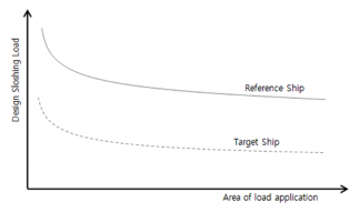
Figure 9 Schematic drawing of comparative method
![]()
(5) Reinforced Comparative Method
(A) The reinforced comparative method include the strength of the cargo containment system in the evaluation process. It is suitable for the case that the structural strength of cargo con-
tainment system of the target ship increases from that of the reference
the standard box of box type cargo containment system(NO 96) is inforced box or the super-reinforced box, this method can be applied.
(B) For the reinforced comparative method, the design sloshing load and containment system for the reference ship and the target ship should
ship. In the case that
improved by the re-
the strength of cargo be obtained. The de-
sign sloshing loads are usually obtained through the model test. It should comply with the
same test procedure with the same model facility for the target ship and the reference ship.
(C) The strength change of cargo containment system are generally obtained by using the finite
element analysis or the model test or both method at the same time. The critical failure
mode of cargo containment system between the reference ship and assessed and documented. Although the structural change of the
the target ship should be target cargo containment
system is to change the critical failure mode, it should be demonstrated that its performance
has not been further degenerated by the additional strength increment.
(D) If the ratio of strength of cargo containment system to the design sloshing load for the tar- get ship is lower than that for the reference ship, the cargo containment system of the tar-
get ship can be approved. Figure 10 shows this conceptually.
ǼẀZYXŸ ZŶ ŸZYYŸX Ŷ ŸŴẀŹŴZXẀŹ ZYYỲ Ĥ ǼẀZYXŸZŶ ŸZYYŸX Ŷ ŸŴẀZẀXẀZẀŸẄẀ ZYYỲ
ÅŹZŹẄŹŹZŴŶ ZŹZẀŸXŹY ŸX ÆÆÅŹŴZXẀŹ ZYYỲ ÅŹZŹẄŹŹZŴŶZŹZẀŸXŹYŸXÆÆÅZẀXẀZẀŸẄẀZYYỲ
(E) If the main design factor(size, arrangement and ratio) of cargo containment system of the target ship change significantly as compared to the that of the reference ship, the reinforced comparative method cannot be applicable. This design as determined as new design is as- sessed through the absolute method.
(F) If the approved design for the reference ship is not present, the absolute applied.
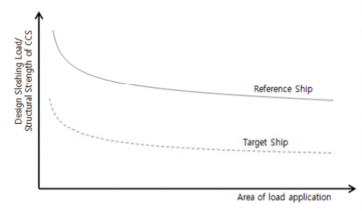
Figure 10 Schematic drawing of enhanced comparative method
method should be
![]()
3. Absolute Method
(1) Step 1 Finite element analysis
(A) General
(a) By applying the maximum load obtained through the sloshing model test as quasi-static load, static analysis is performed.
(b) The analysis target is generally the pre-fabricated unit at manufacturing process step.
(c)
If necessary, it may include a hull in the analysis and consider the temperature of the cargo containment system and the motion of cargo hold.
(B) Element and material properties
(a) In step 1 finite element analysis, modeling does not include LNG.
(b) The layered foam type cargo containment system is composed of the polyurethane foam(PUF), the plywood and the mastic as a laminated structure. Figure 11 shows the model section.
(c)
It is assumed that the mastic is isotropic and the plywood is orthotropic. Polyurethane foam can be selected to be isotropic or orthotropic as needed.
(d) The layered foam type cargo containment system(Mark III) does not include the primary
barrier(STS 304L) and the secondary barrier(Triplex) in the finite element model. These
two barriers are not included in the analysis model due to minor contribution porting the structural stress caused by sloshing.
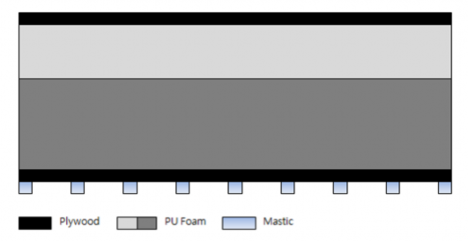
Figure 11 Configuration of layered foam type cargo containment system(Mark III)
to sup-
(e) The box type cargo containment system is composed of the primary insulation box, the secondary insulation box and the mastic as three main elements. Figure 12 show the model geometry.
(f) It is assumed that the mastic is isotropic and the plywood constituting the insulation box has the orthotropic behavior.
(g) Invar forming the primary barrier and the secondary barrier of the box type cargo con- tainment system is not included in the finite element model. The primary barrier and the secondary barrier is not included in the analysis model due to its minor contribution
to supporting the structural stress caused by sloshing.
(h) Material properties of the mastic, the plywood and the polyurethane foam necessary for step 1 finite element analysis should be provided by the manufacturer. It is a principle.
![]()
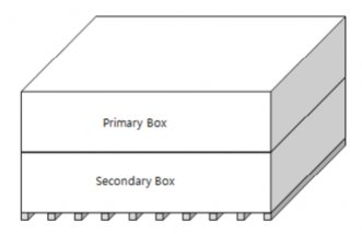
Figure 12 Configuration of box type cargo containment system(NO 96)
(C) Finite element mesh
(a) The three-dimensional finite element model of the layered foam type cargo containment system should use the hexa solid element as the default. The finite element mesh
should be sufficiently dense to obtain the converging result for the layered foam type cargo containment system and the box type cargo containment system.
(b)
(c)
(d)
The mastic should be divided into two or more elements in the thickness direction and the width direction. The upper plywood should be divided at least one or more element
in the thickness direction. Lower plywood should have at least three or more elements in the thickness direction. The plywood elements between the two mastic should be at
least seven or more elements. Polyurethane foam should be divided into elements with a length of about 10mm in the thickness direction.
The box type cargo containment system should be modeled using the shell elements.
The enhanced plywood can be considered by increasing the thickness of shell element. The perlite in the box is not considered because they do not affect the strength of car- go containment system.
For the box type cargo containment system, space between two mastics should be div- ided into at least seven or more shell elements. The primary box and the secondary box should be divided into elements with a length of about 10mm in the thickness direction.
(e) The finite element model for the layered foam type cargo containment system is in Figure 13.
shown
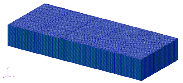
Figure 13 The finite element 3-D mesh model of cargo containment system
![]()
(D) Loading and boundary conditions
(a) The height direction of the mastic part in contact with hull is restrained. Figure 14 shows an example which is fixed on mastic in the height direction in the layered foam type cargo containment system.
(b)
(c)
The mastic part closest to the four vertices of the cargo containment system are con-
strained in three directions so at to avoid the rigid body motion. Figure 15 is an exam- ple to show the three direction constraints of the four part of mastic in the layered foam type cargo containment system. The boundary conditions of (a) and (b) are in- dicted in detain in Table 3.
The static load is applied on the top plywood of cargo containment system. Figure 16 shows an example applying a static load on the layered foam type cargo containment
system. The static load Figure 5.
is obtained from the model test, which means Āmax defined in
Table 3 Boundary Conditions
Position | Displacement | Rotation | ||||
ǾŻ | ǾŻ | Ǿa | PŻ | PŻ | Pa | |
Mastic nodes in contact with hull | 0 | 1 | 0 | 0 | 0 | 0 |
Mastic nodes closest to the four vertices of cargo containment system | 1 | 1 | 1 | 0 | 0 | 0 |
(Notes) 1 : Constrained 0 : Free | ||||||
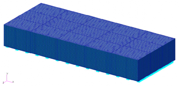
Figure 14 The constrained boundary conditions of mastic in height direction in cargo containment system
![]()
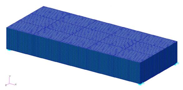
Figure 15 The constrained boundary conditions of mastic corner area of cargo containment system
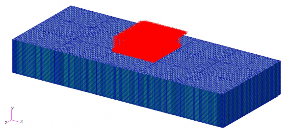
Figure 16 Loading conditions of sloshing for cargo containment system
(d) Application location of static load is to be determined with reference to the model test.
In general, the pressure sensor is arranged surface area of 1m2 in the model test. In
in a 3×3 or 4×4 panel with respect to the this condition, the combination of the pres-
sure sensor shown in Figure 17 is obtained. The static analysis should proceed consider- ing this combination.
(i) 1×1 sensor array : 9set
(ii) 3×1 or 1×3 sensor array: 6set
(iii) 2×2 sensor array: 4set
(iv) 3×2 or 2×3 sensor array: 4set
(v) 3×3 sensor array: 1set
![]()
Figure 17 Examples of applied area combination for sloshing loads
(E) Buckling Strength of Box Type Containment System(NO 96)
Because of the characteristics of box type cargo containment system, the buckling occurs. The linear buckling analysis is carried out with the finite element model in order to evaluate the static strength of the box type cargo containment system. Figure 18 shows an example of buckling analysis.
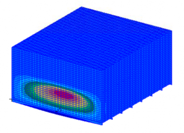
Figure 18 Analysis example of linear static buckling of box type cargo containment system(NO 96)
(F) Analysis Procedure
In step 1 of finite element analysis, the static analysis for the model not including using a approved code by the Society is to be performed.
LNG by
It is possible to obtain stress, strain and displacement from the result of finite element analysis. The analysis procedure is as follows.
(a) The polyurethane foam, the plywood and the mastic of the layered foam type cargo
containment system are to be modeled according to (B) and (C). The boundary con- dition in accordance with (D) is applied to the mastic and the sloshing load is applied to the upper plywood as the quasi-static pressure.
(b) The box type cargo containment system is to be modeled as the primary insulation box, the secondary insulation box and the mastic according to (B) and (C). According to (D),
![]()
the boundary condition is applied to the mastic and the sloshing load is applied to the upper surface of the primary insulation box as the quasi-static pressure. The static struc- tural finite element analysis is to be performed. A linear buckling analysis is to be conducted.
(c) Based on the analysis result, the process of structural evaluation for each element proceeds.
(d) The analysis result should not be more than the acceptance criteria according to 4.
(e) If the result exceed the acceptance criteria, step 2 finite element analysis proceeds.
(2) Step 2 finite element analysis
(A) General
(a) The finite element shape, the element partitioning and the size, material properties and boundary conditions should be accordance with (1).(A)~(D).
(b) The analysis target generally refers to the pre-fabrication unit in the manufacturing proc- ess step.
(c)
(d)
If necessary, it may include a hull in the analysis and consider the temperature of the
cargo containment system and motion of cargo hold
By applying the triangular impact pressure obtained from the sloshing model test, the dynamic analysis is to be performed.
(e) Since the step 2 finite
element analysis is the dynamic process, the time increment
should be small enough that analysis result such as the stress, the strain and the dis-
placement is possible to
obtain. Time increment shall be suitably selected based on the
analysis code used. In the implicit code, the time increment should be less than 1/20 of the natural period of the analysis model. The time increment in the explicit code should be determined in proportion to the finite element mesh size. For example, the sound speed in the steel and aluminum is 5mm/1Rs. Thus, if the steel structure finite element
model is modeled by 5mm, time increment is 1Rs. Elements of material having a smaller sound speed can have a larger time increments. Table 4 shows the sound wave velocity for various materials.
Table 4 Sound speed for various materials
Material | Sound speed(m/s) |
Air | 331 |
Water | 1478 |
Steel | 5240 |
Since the sound speed of the material with a constant elasticity modulus is calculated as follows, the appropriate size for each of the finite element should be modeled based on this.
JÁJ FË G R F
Ẅ G ĬFË Ğ Ρ̓ FFË G ËΡ̓ FŘ
Á : Material elasticity modulus
Ρ̓ : Material poisson's ratio
Ř : Material density
(f) The analysis time should be more than three times the duration of sloshing load. If the desired analysis result is not obtained, the analysis duration is to be adjusted.
(B) Element shape and material properties It proceeds following (1)(B).
(C) Finite element mesh
It proceeds following (1)(C).
(D) Loading and boundary conditions
(a) Boundary conditions follows (1)(D)(a) and (b).
![]()
(b) The dynamic triangular wave as design sloshing load is applied on the top plywood of cargo containment system. This pressure is determined by the model test. The sloshing dynamic triangular wave is defined by the maximum pressure, the rising time, the drop time and the skewness. Figure 5 shows an example of dynamic sloshing triangular wave.
(c)
The sloshing impact pressure has a variety of effects on the cargo containment system as various parameters(the maximum sloshing pressure, the rising time, the drop time and the skewness) defined in Figure 5 changes. In order to investigate it, the parametric study for each factor should be performed. It is possible to investigate the influence of the factors for each acceptance criteria and parameter range to be considered may be selected. In applying the parametric study, the designer should consult with the Society in advance and determine how to apply the each parameter, etc.
(d) The
test.
4×4
area applied by the sloshing impact pressure should be consistent with the model In model test, area of 1m2 is usually covered with a pressure sensor of 3×3 or
panel. Various combinations of the pressure sensor are described in (1)(D)(d). By
implementing the dynamic finite element analysis for the various combination, the struc- tural assessment for cargo containment system should be proceeded.
(E) Buckling of Box Type Containment System(NO 96)
It proceeds following (1)(E).
(F) Analysis Procedure
Step 2 finite element analysis is performed according to the following sub steps.
(a) As described in the previous part, the layered foam type cargo containment system (Mark III) should include a polyurethane foam, plywood and mastic, the box type cargo containment system(NO 96) is to include the primary insulation box, secondary in- sulation box and mastic. Boundary conditions described in previous part are applied to the lower part of mastic and the sloshing dynamic triangular pressure to the top ply- wood of cargo containment system as loads. The dynamic structural finite element anal- ysis is to performed.
(b) The box type cargo containment system is to perform a linear buckling analysis, also.
(c)
Time history for stress/displacement by calculating the stress distribution and the dis-
placement distribution for each component of cargo containment system are obtained.
(d) It proceeds by performing the parametric studies with factors of sloshing load on the ef- fects of the stress/displacement.
(e)
The structural strength assessment of cargo containment system should be proceeded by performing the finite element analysis for various combinations of applied area for slosh-
ing impact load according to (1)(D)(d).
(f) The analysis results should be less than or equal to acceptance criteria according to 4.
Figure 19 shows an example of comparing the strength of cargo containment the sloshing load of cargo containment system conceptually.
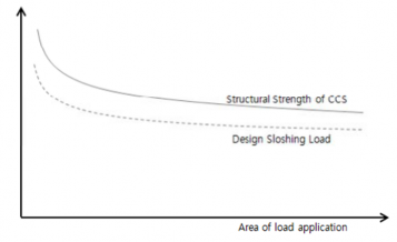
Figure 19 Comparison between structural strength of cargo containment system and sloshing load
system to
![]()
4. Acceptance Criteria
(1) General
(A) The designer is responsible for deriving the acceptance criteria and the purpose of this sec- tion is to provide the guidance to derive the acceptance criteria.
(B) A typical failure type of layered foam type cargo containment system under the sloshing
loads are as follows. A common occurrence position of the damage is shown in Figure 20.
(a) Failure of polyurethane foam
(b) Plywood distortion
(c) Peeling of lower plywood
(d) Breaking of plywood at the connection between mastic and lower plywood
(e) Breaking of polyurethane foam at the connection between mastic and lower plywood
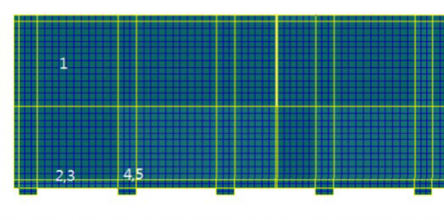
Figure 20 Typical damage location of layered foam type cargo containment system
(C) The typical damage in the box type cargo containment system is as follows.
(a) Buckling of the primary insulation box or the secondary insulation box
(b) Failure due to the bending/shear of the top plywood
(D) The damage of cargo containment system may be evaluated from the point of yield/fracture, buckling and service limit. The damage type is related with material properties such as the relationship between stress and strain, yield strength and tensile strength.
(E) For the viewpoint of yield/fracture and damage, the maximum tensile/compressive stress and the shear stress of plywood is evaluated. The von-mises stress of polyurethane foam and mastic is compared to its tensile strength for the assessment of structural strength.
(F) If the sloshing load exceeds the critical buckling load from the viewpoint of assessment of buckling failure, the cargo containment system is deemed to be broken.
(G) Related to the service limit, the polyurethane foam, the plywood and the mastic has the al- lowable maximum displacement. If this limit is exceeded, the system becomes unstable and results in failure finally.
(H) Evaluation method of 2 should satisfy the acceptance criteria of (2) and (3), The evaluation method of 3 should be in accordance with the acceptance criteria of (4).
(2) Comparative method
In the case that the design sloshing load of the target ship is less than that of the reference ship, the cargo containment system of the target ship may be approved.
ĀŹŴZXẀ Ź Ĥ ĀZẀ XẀZẀŸẄẀ
ĀŹŴZ XẀŹ
ĀZẀXẀ ZẀŸẄẀ
: Design sloshing load of target ship
: Design sloshing load of reference ship
This criteria should be satisfied for the area/sloshing loads as shown in Figure 9.
![]()
(3) Reinforced Comparative Method
If the ratio of structural strength of cargo containment system to the design sloshing load for the target ship is less than that of the target ship, the cargo containment system of the target ship can be approved.
ĀŹŴZXẀŹ ĀZẀXẀZẀŸẄẀ
JÆ
J
Ĥ
Æ ŹŴZXẀŹ ZẀXẀ ZẀŸẄẀ
ĀŹŴZ XẀŹ
ĀZẀXẀ ZẀŸẄẀ
ÆŹŴZ XẀ Ź
ÆZẀXẀ Z ẀŸẄẀ
: Design sloshing load of target ship
: Design sloshing load of reference ship
: Structural strength for cargo containment system of target ship
: Structural strength for cargo containment system of reference ship
This criteria should be satisfied for the area/sloshing loads as shown in Figure 10.
(4) Absolute Method
(A) In the case that the ratio of design sloshing load to the structural strength of cargo contain- ment system is less than the utilization factor selected appropriately, the cargo containment system can be approved.
Ā Ĥ ÃÁ
JÆ
Ā : It is the design sloshing load which includes the effect of loading area, rising time and drop time, etc.
Æ : It means the structural strength of cargo containment system and evaluated by the structural analysis.
ÃÁ : As the utilization factor, the value less than 0.60 is generally used. 0.60 is de- termined by the approximation of 1/(1.1×1.5). 1.5 is commonly used parameter for the dynamic load and 1.1 is a normally used factor for strength.
Application of the utilization factor will vary depending on whether or not the cargo containment system is verified design. For the new cargo containment sys- tem, the utilization factor less than 0.5 is generally used.
(B) In order to evaluate the structural strength of cargo containment system, the analysis should be performed based on the following criteria. The designer is responsible for the selection of criteria.
(a) The maximum normal stress : The maximum normal tensile/compressive stress in three direction(X, Y, Z coordinate) shall satisfy the following conditions.
Ŗmax ≤ ŖẄ
ŖẄ : It is the allowable normal stress which represents ÅŶ ŖŻ or ÅŶ ŖŹ .
ŖŻ : It is the yield strength which should be based on the acknowledged experimental data for each material and the standard recognized by the Society
ŖŹ : It is the tensile strength which should be based on the acknowledged experimental data for each material and the standard recognized by the Society
ÅŶ : It is a strength reduction factor given in Table 5.
![]()
(b) The maximum shear stress : The maximum shear stress should satisfy the following conditions.
Ŗmax ≤ ŖẄ
(c)
ŖẄ : It is the allowable shear stress which represents ÅŶ ŖŹ .
ŖŹ : It is the shear strength which should be based on the acknowledged experimental data for each material and the standard recognized by the Society.
ÅŶ : It is a strength reduction factor given in Table 5.
The maximum equivalent stress : The maximum equivalent stress should meet the fol- lowing conditions.
Ŗ
Ẁ Ỳ
max
≤ ŖẄ
ŖẄ : It is the allowable equivalent stress which represents ÅŶ ŖŻ or ÅŶ ŖŹ .
ŖŻ : It is the yield strength which should be based on the acknowledged experimental data for each material and the standard recognized by the Society
ŖŹ : It is the tensile strength which should be based on the acknowledged experimental data for each material and the standard recognized by the Society
ÅŶ : It is a strength reduction factor given in Table 5.
(d) Buckling criteria : By performing the buckling analysis for the box type cargo contain- ment system, the allowable buckling pressure should be obtained. The maximum pres- sure applied to the top box should satisfy the following conditions.
Āmax ≤ ĀẄ
ĀẄ
ĀẄZ
ÅŶ
: It is the allowable buckling pressure which represents ÅŶĀẄZ .
: It is the critical buckling pressure which should be based on the acknowledged experimental data for each material and the standard recognized by the Society
: It is a strength reduction factor given in Table 5.
Table 5 Strength reduction factors
SRF | Tensile strength | Shear strength | Yield strength | Buckling pressure |
Sm | 0.8 ~ 1.0 | 0.8 ~ 1.0 | 0.9 ~ 1.0 | 0.9 ~ 1.0 |
(e) Service limit criteria : If there is a maximum displacement recommended by designer for each component of cargo containment system, it should satisfy the following conditions.
Źmax ≤ ŹẄ
Źmax : It is a analysis result which represents the maximum displacement.
ŹẄ : It is allowable service displacement which should be recommended by the designer.
![]()
5. Material Properties
(1) General
(A) The designer is responsible for getting the material properties used in the structural analysis.
The purposes of this section is to provide the guidance to draw material properties.
(B) To evaluate the material mechanical properties including a dynamic effect due to the slosh- ing loads and the cryogenic environment of LNG(approximately -163°C) is the responsibility of the designer.
(C) Material properties can be obtained through the material supplier, the promulgated ex- perimental data or the material experiments. They should be sought in accordance with (2), (3), (4) and (5).
(2) Primary and secondary barriers
(A) Primary and secondary barriers(Membrane and Triplex of Mark III, Invar of NO 96 and in- var and triplex of CS 1) should be modeled as a linear isotropic elastic material. It is nec- essary to enter the following properties.
(a) Density(kg/m3)
(b) Young's Modulus(MPa)
(c) Poisson's ratio
(B) If necessary, the analysis shall include the change of material properties with the change of temperature.
(3) Polyurethane Foam
(A) The layered foam cargo containment system shall be modeled as a linear isotropic elastic material, it is necessary to enter the following properties. The polyurethane foam can be modeled to have a perpendicular anisotropy, if necessary.
(a) Density(kg/m3)
(b) Young's Modulus(MPa)
(c) Poisson's ratio
(d) Shear modulus(MPa)
(B) The analysis shall include the change of material properties with the ambient temperature and a cryogenic temperature.
(4) Plywood
(A) The plywood is a composite material consisting of several layers of wood. The behavior of
the plywood should be modeled to have a perpendicular anisotropy, the following properties should be entered.
(a) Density(kg/m3)
(b) Young's Modulus in three direction(MPa)
(c) Poisson's ratio
(d) Shear modulus(MPa)
(B) Analysis shall include the change of material properties with ambient temperature and a cryogenic temperature.
(5) Mastic
(A) The mastic to connect the hull structure to the cargo containment system shall be modeled using a linear isotropic elastic material. The following properties is needed to be entered.
(a) Density(kg/m3)
(b) Young's Modulus(MPa)
(c) Poisson's ratio
(d) Shear modulus(MPa)
(B) The parameters for the ambient temperature is used for the analysis.
![]()